
MICROSTRIP IMPEDANCE CALCULATOR
Microstrip Impedance Calculator
(1 oz copper = 1.37 mils) (FR-4 is typically 4.2 – 4.5)
Characteristic Impedance (Z0): — Ω
Understanding Controlled Impedance in PCB Design
As signal speeds increase, PCB traces can no longer be treated as simple wires. They behave as transmission lines. If the impedance of the trace doesn’t match the source and load impedance, signal reflections occur, leading to data corruption and EMI issues.
The Microstrip Formula
The characteristic impedance (Z0) of a microstrip is determined by the physical dimensions of the trace and the properties of the dielectric material (usually FR-4). The standard formula (IPC-2141) used in this calculator is:
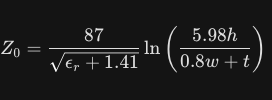
Where:
- w = Trace Width
- t = Trace Thickness (1.37 mils for 1 oz copper)
- h = Dielectric Thickness (distance to ground plane)
- ϵr = Dielectric Constant of the substrate
Key Guidelines for High-Speed Design:
- Target 50 Ohms: Most single-ended high-speed signals (like clock lines) target 50 Ω.
- Differential Pairs: For USB or Ethernet, you need two traces coupled together. Their Differential Impedance is usually around 2×Z0×(1−0.48⋅e−0.96⋅hs), where s is the spacing between traces.
- Reference Plane: Never route high-speed signals over gaps in the ground plane, as this causes an impedance spike and destroys signal integrity.