
Clock Divider
A digital clock divider is typically implemented using a counter that increments on every rising edge of the input clock (fin).
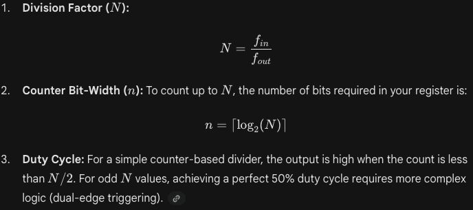
The Core Formulas:
Clock Jitter: Simple digital dividers can introduce jitter, especially if the input clock isn’t stable. For high-precision RF or audio applications, use a PLL (Phase-Locked Loop) or DCM (Digital Clock Manager) instead of a counter-based divider.
Odd Division: Dividing by an odd number (like 3 or 5) and maintaining a 50% duty cycle is tricky. It usually requires ORing or ANDing two clocks that are triggered on different edges (Rising and Falling).
Power Consumption: Every time a flip-flop toggles, it consumes power. In low-power designs, scaling down the clock frequency (f) for non-critical peripherals is the most effective way to reduce dynamic power (P∝f)