
Patch Designer
Feed point should be recessed ~1/3 from edge for 50Ω match.
A rectangular patch antenna is a radiating element on one side of a dielectric substrate with a ground plane on the other.
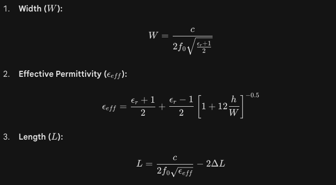
The Physics: The length (L) determines the resonant frequency. Because of “fringing fields” at the edges, the patch looks electrically longer than its physical size, requiring a correction factor (ΔL).
Core Formulas:
FR-4 vs. Rogers: While FR-4 (ϵr≈4.4) is cheap, it has high losses at frequencies above 2 GHz. For high-performance antennas, engineers use materials like Rogers 4350B which have a stable ϵr and very low loss tangent.
Feeding Method: The simplest way to feed a patch is a microstrip line or a coaxial probe. To match the antenna to 50Ω, the feed point is usually moved away from the edge toward the center (the “inset feed”).
Bandwidth: Patch antennas are notoriously narrow-band (typically 1–5%). To increase bandwidth, you can increase the substrate height (h), though this may increase surface wave losses.