
RC Resonance
Attenuation at cutoff is -3dB (70.7% Voltage).
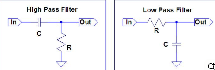
An RC filter consists of a resistor (R) and a capacitor (C). The configuration determines whether it is a Low Pass (passes DC, blocks high frequencies) or a High Pass (blocks DC, passes high frequencies).
The Mathematics: The cutoff frequency is defined as the point where the output power is half the input power (the -3dB point).
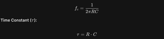
This represents the time it takes for the capacitor to charge to approximately 63.2% of the input voltage.
Input/Output Impedance: For an RC filter to work as calculated, the source impedance should be much lower than R, and the load impedance should be much higher than R. If not, the impedances will "loading" the filter and shift the cutoff frequency.
Phase Shift: At the cutoff frequency, the filter introduces a 45° phase shift between the input and output.
Roll-off: A simple single-stage RC filter has a roll-off of 20dB per decade (or 6dB per octave). If you need a sharper "wall," you need to cascade multiple stages (Active Filters).